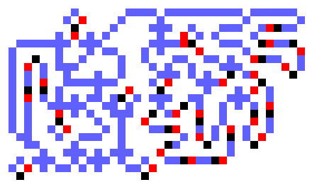
Karl Scherer's 6-bit, 6-tick Binary Multiplier

As far as I know, the first binary multiplier was designed by Brian Trial. I appeared on MathPuzzle on August 6, 2002. It is an 8-bit by 8-bit multiplier that takes about 18000 ticks to produce the product. Although quite large, it easily fits into an MCell file.
A breakthrough in WireWorld design!
An improvement to Brian's design was also posted on MathPuzzle, only a few days later on August 18, 2002. (Nick must have had a few nights with very little sleep.) His design is also an 8-bit by 8-bit version with 16 specific flip-flops to hold the product. A full adder is included with each flip-flop. The cycle time of the logic is 15 ticks. So it takes about 15 n2 ticks to perform an n-bit by n-bit multiply. The 8-bit multiplier takes a little over 1000 ticks.
Quite amazing to watch!
Karl's design has a single full adder and no explicit flip-flops. Instead there are loops of WireWorld cells that allow electrons to pass through random logic, signals being separated by 6 cells in each loop. There are 5 loops - one for the clock, one for each multiplier, one for the product, and one for a reset to a gating latch. Karl gives a 6-bit by 6-bit version that fits into the very small area of 49x49 cells. He did his design work in Zillions of Games. With n passes through the full adder, a product of 2*n bits, and 6-tick logic, the operation take about 12 n2 ticks. About a 20% improvement in time over Nick's design.
A quantum improvement in multipliers!
With Karl's permission, I'm showing his multiplier here, but in MCell format, to keep consistency with the rest of the pictures. His design was done in Zillions, and is presented at his web site using that format.
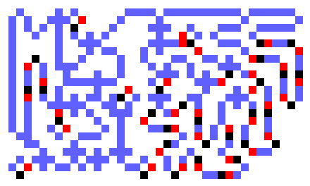
My designs are offshoots of Karl's. There is a single full adder and no explicit flip-flops for the data or clock. Two latches do exist, one for the carry signal and one for gating.
The main differences between my design and Karl's are the following
Using 4-tick logic means the operation takes about 8 n2 cycles, about 1/3 faster than Karl's 6-tick design. The logic optimization also makes for a very compact machine.
Tiny and Fast!
There are 6 components in each of the multipliers
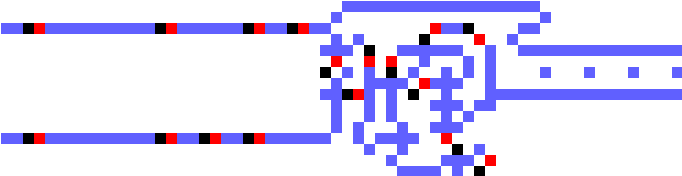
Amazingly, the full adder generates a new partial product bit every 4 ticks. There are two inputs to the FA, PRODi and MULTBi. The FA also needs the carry bit, CARRYi-1, with is held in an RS-Latch within FA. The output of FA is the next partial product bit, SUMi. It must also update the CARRY latch. The equations are
These equations may appear clumsy, however, they obtain the desired result without the need for a cross element. The full adder was designed to minimized the area of the entire multiplier, not the area of the full adder. After many tries, these equations gave an implementation that allows the carry latch to be most advantagously placed, so as to allow the final sum bit to exit to the east.
A full adder is given at the end of this page that was designed with the criterion of minimum area.
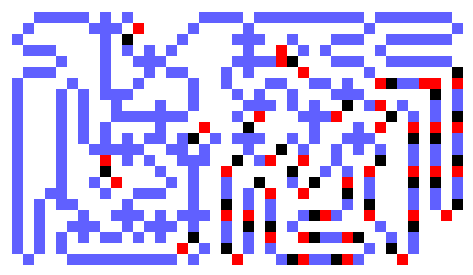
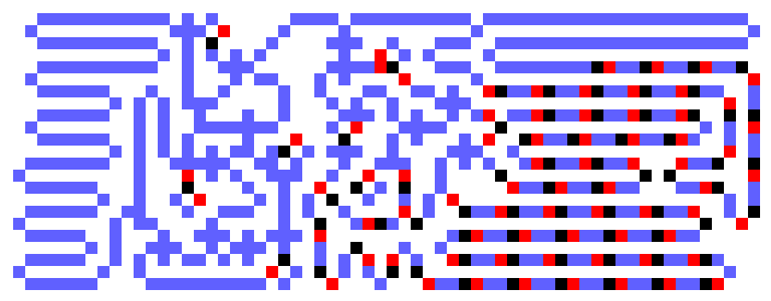
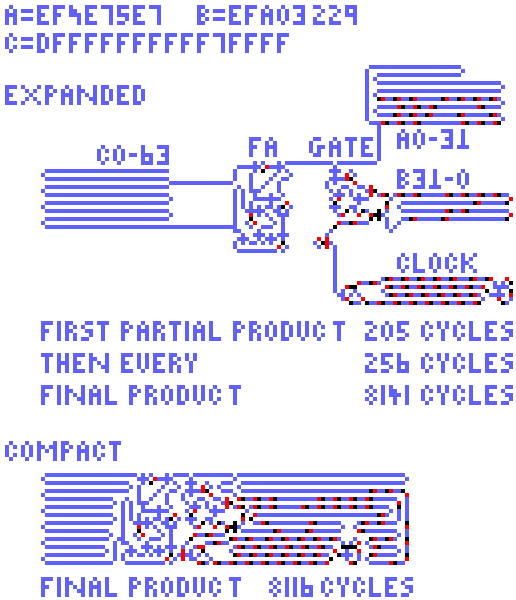
Five versions of the multiplier are given: 5-bit, 6-bit, 8-bit, 16-bit, 32-bit, and 64-bit. Each one multiplies two n-bit numbers (A and B) giving a 2*n-bit product (C).
The 5-bit multiplier has a 40-cell product loop. I could not come up with a design whose product loop was 32, the next acceptable shorter loop length. This means a 5-bit by 5-bit multiply can be done in about 8 * 52 = ticks. (The actual number is 232, which includes the time for the first bit to propagate through the FA). A 4-bit by 4-bit multiply would take about the same time.
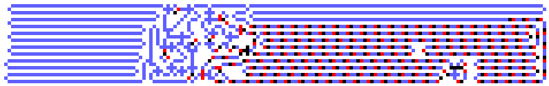
Larger multipliers are obtained by merely increasing the loop lengths. I did a 6-bit to compare to Karl's, an 8-bit to compare to Brian's and Nick's. I originally set out to get a 64-bit version, so just did all powers of two from 8 through 64.
The 32-bit version is the one that is posted on MathPuzzle.
There is one difference beginning at the 32-bit version. A fill-empty ring counter is used for the clock instead of a simple loop. The ring counter is about half the length of a simple loop, however, some logic is required to make it fill-empty and to decode the clock. In the 16-bit version and smaller the extra logic is greater than the savings of halving the length.
The MCell Source Code. You'll need Mirek's Cellabration to run it.
The MCell Source Code.
The MCell Source Code.
The MCell Source Code.
The MCell Source Code for output mostly ones and input ones..
The MCell Source Code.
| n | Loop Lengths | Area | Op Time | Clock | MultA | MultB | Product |
|---|---|---|---|---|---|---|
| 5 | 36 | 16 | 36 | 40 | 22x38 | 232 |
| 6 | 44 | 20 | 44 | 48 | 22x38 | 316 |
| 8 | 60 | 28 | 60 | 64 | 23x41 | 532 |
| 16 | 124 | 60 | 124 | 128 | 23x62 | 2036 |
| 32 | 128 | 124 | 252 | 256 | 23x92 | 8116 |
| 64 | 256 | 252 | 508 | 512 | 23x157 | 32564 |
The length of the product loop is 8*n. The length of the MultB loop is 4 less than the product loop. The length of the MultA loop is half of 4 less than the MultB loop. The period of the clock is the same as the length of the MultB loop. So for small n its loop length is the same as MultB, but for large n, when a fill-empty ring is used, it's half of the product loop. The total time for the multiply operation is given by
The full adders in the above multipliers were designed to minimize the area of the multipliers, not the full adders. The fa given here is the minimum-area 4-tick design I came up with. It uses basically the equations of David Moore and Mark Owens' multipliers, but with 4-tick logic elements. Complex logic gates are used throughout.
The transit time is 21 ticks and it resides in a 14 by 16 rectangle, not including the top wire that is used only to aid viewing. Suprising, perhaps, this area is less than the those of the 6-tick versions found on net.
It is set up to do binary 1001011 plus 1001110 equals 10011001.
Fa's are also found on Karl's web site.
The MCell Source Code.